Please read the complete instructions before you start !
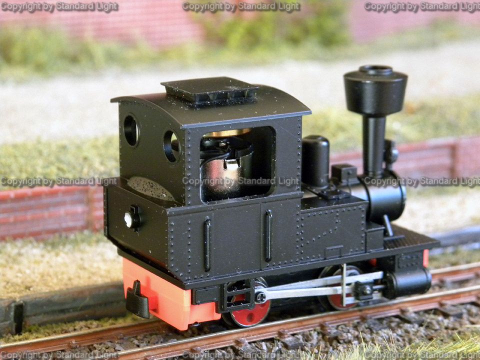 |
Das
Umbauopfer : die O&K Lok The victim: an original Koppel locomotive. |
 |
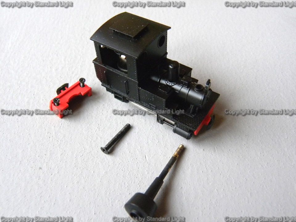
Lösen
der
3 Schrauben, die hinteren beiden nur soweit herausdrehen, daß
das rote
Kunststoffteil abgehoben werden kann. Die mittlere Schraube ganz
herausdrehen,
die Achsabdeckung aber NICHT lösen. Anmerkung vom Webmaster: Die Achsabdeckung lässt sich zerstörungsfrei nicht lösen !!! Loosen the shown three screws. The two screws in the rear part loosen only until you can remove the rear coupler bank. The screw in the middle is completely removed. Do not try to remove the axle cover ! |
 |
Nun
den
Schornstein herausdrehen Now remove the stack (yes this works also for the straight stack version ) |
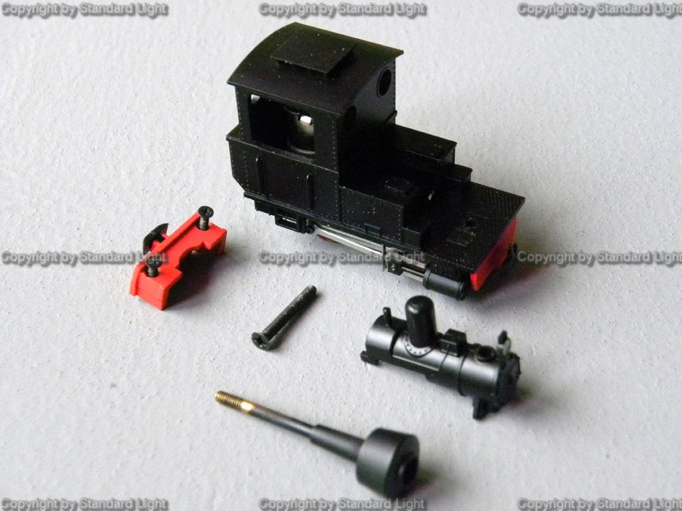 |
Danach
lässt sich der kleine Kessel nach vorn
herausziehen Now you can remove the boiler setup by pulling it to the front. Watch lamp and whistle not to be touched too much ! |
 |
Nun
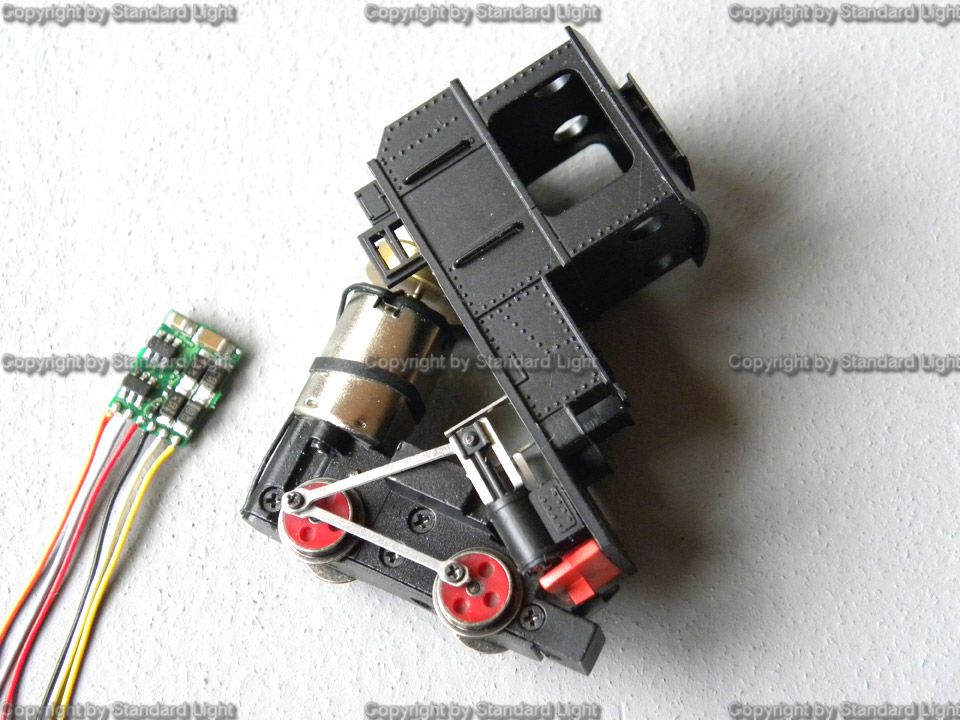
lässt sich das Gehäuse vorsichtig nach oben anheben. Da der Decoder an der Rückseite des Motors angebracht wird, müssen die Kuppelstangen bei vorsichtiger Handhabung nicht gelöst werden. The cab can now carefully be lifted. As the decoder is mounted on the rear of the motor the coupling and driving rods must not be unscrewed. While lifting the cab watch the rods passing the metal body of the chassis without beeing exposed to high forces. |
 |
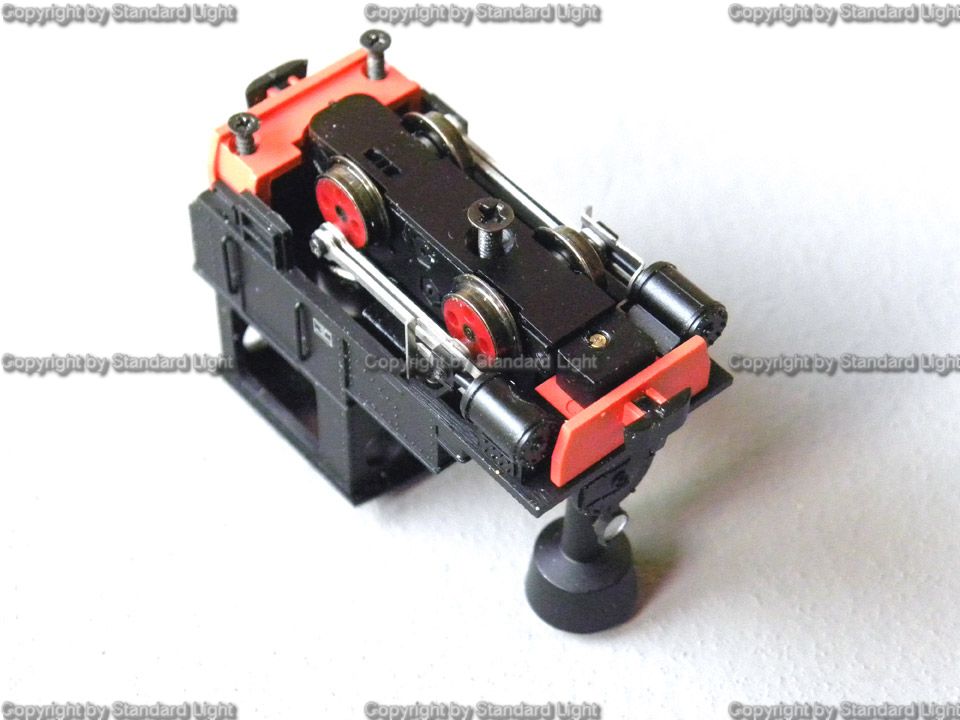
So
sieht
es dann von hinten aus. View after all this from behind |
 |
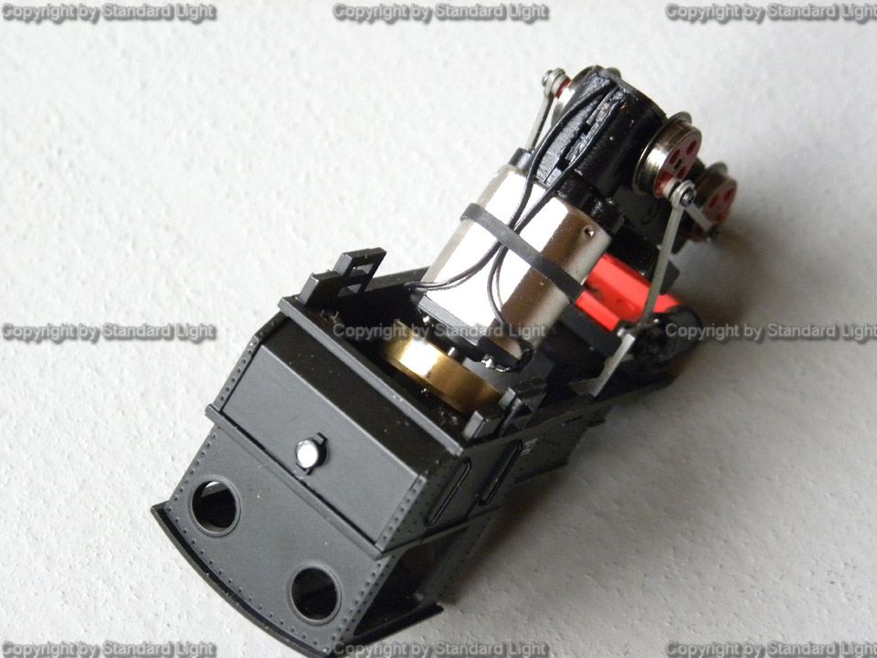
Nun das Gummiband
durchtrennen, die beiden Kabel in Höhe der
Motorunterkante
trennen und ein Stück doppelseitiges Klebeband auf den Motor
kleben. Nun muss entschieden werden, ob die Kabel direkt an den Decoder gelötet werden oder, falls der Decoder mal getauscht werden muss, an diesem kleine Kabelenden stehen bleiben. Now cut the rubber tape and the cables at the lower end of the motor. Place a piece of double sided tape onto the motor. Now needs to be decided wether the cables are soldered directly to the decoder - or for possibly easier later modifications to small ends of cable that are attached to the decoder (as shown). |
 |
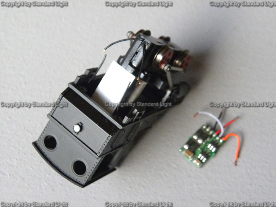
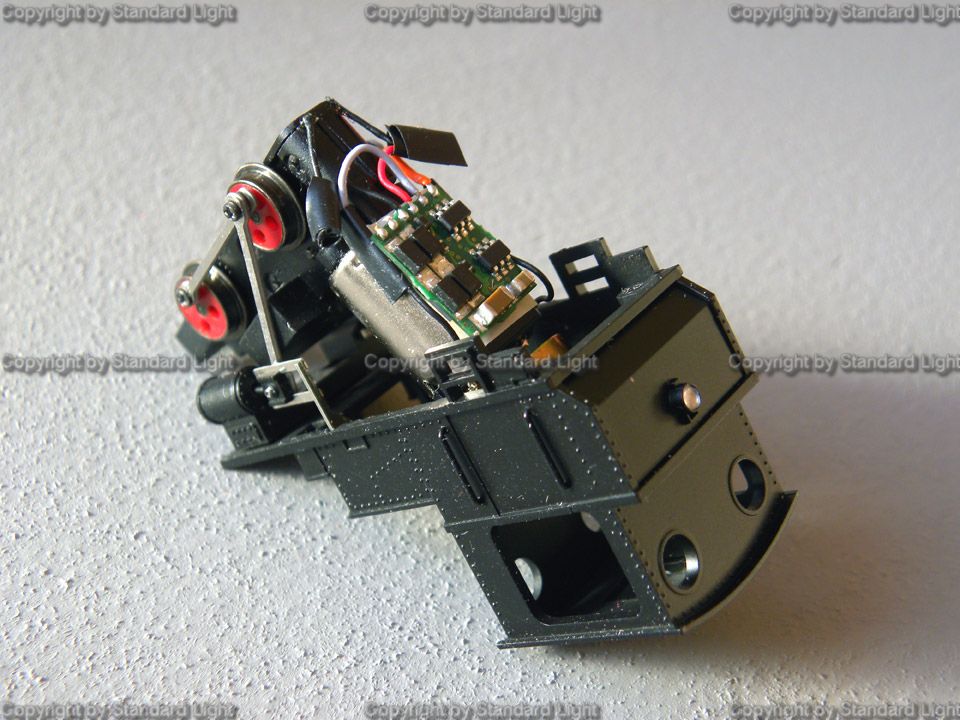
Hier wurde die
Tauschmöglickeit berücksichtigt. die Kabelenden des Decoders leicht in Form biegen. Zweckmäßigerweise jetzt den Decoder auf dem Klebeband befestigen und erst die Kabel, die vom Motor kommen anlöten. Die Lötpunkte mit Isolierband versehen. Here the possibility for later modifications was choosen. Place the decoder onto the tape, bend the short cables for easier soldering into the desired position. Solder the cables together and isolate the solder joints with some tape. |
 |
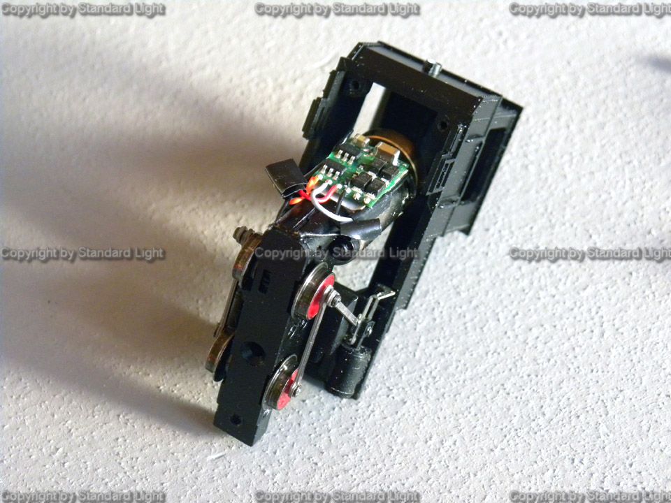
Nun die unteren
Kabel an die verbleibenden Enden vom Decoder anlöten und
ebenfalls isolieren. Der gesamte Antriebsblock kann nun in das Gehäuse wieder eingeschoben werden. Hierbei ist nur darauf zu achten, kein Kabel einzuklemmen. Now solder the lower ends of the cables also to those coming from the decoder. The whole chassis can now moved back into the cab. Watch that no cable gets squeezed anywhere. |
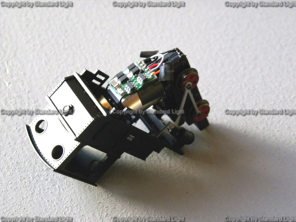 |
Hier noch mal eine
andere Ansicht. Der Zusammenbau erfolgt nun folgender Maßen. Zuerst den kleine Kessel wieder einsetzen, und die lange Schraube von unten durchführen. Noch nicht festanziehen, sondern den Schornstein jetzt, ebenfalls noch locker, einschrauben. Nun die beiden hinteren Schrauben befestigen und das Fahrgestell ausrichten. Sitzt alles perfekt, alle Schrauben anziehen. Aber, nach fest kommt ab!! Here another view. Now put everything back following these steps: Insert the boiler and the long screw from underneath. Do not fix this screw fully at this time. Insert the smokestack and fix it loosely. Now fix the two rear screws with the coupler bank , straighten the chassis in its position and fix the screws. Fix them to hard and you will break something ! |
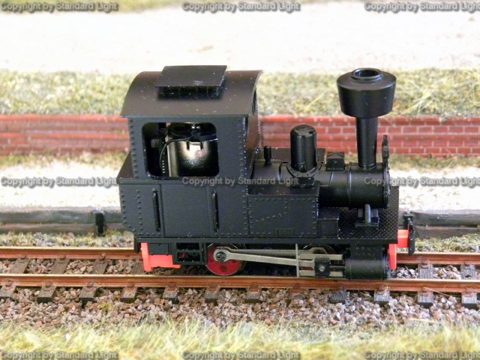 |
So
sieht
es nach dem Umbau aus! Everything is done ! |
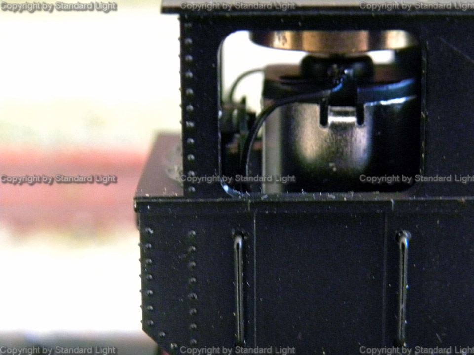 |
Blick
ins Führerhaus View into the cab |